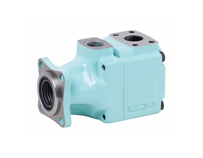
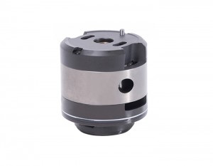
T6GCC/T7GCB/T7GBB Series Double Vane Pump
T6GCC/T7GCB/T7GBB Series Double Vane Pumps

Model Designation
| T6GCC | -B25 | -B17 | -6 | R | 02 | -B | 1 | 10 |
| Series | Shaft end pump displacement |
Cover end pump displacement |
Shaft type | Rotation | Outlet port positions | Design number |
Sealing level | Port dimensions |
| T6GCC | B03、B05、B06、 B08、B10、B12、 B14、B17、B20、 B22、B25、B28、 B31 |
B03、B05、B06、 B08、B10、B12、 B14、B17、B20、 B22、B25、B28、 B31 |
See shaft size | View from shaft end of pump R-ClockwiselCW) Counterclockwise(CCW) |
See pic below | B | 1-S1, NBR 5-S5,Fluorine rubber |
00.01.10.11 See Installation Dimensions |
| T67GCB | B03、B05、B06、 B08、B10、B12、 B14、B17、B20、 B22、B25、B28、 B31 |
B02、B03、B04、 B05、B06、B07、 B08、B10、B12、 B15 |
||||||
| T7GBB | B02、B03、B04、 B05、B06、B07、 B08、B10、B12、 B15 |
B02、B03、B04、 B05、B06、B07、 B08、B10、B12、 B15 |
B03:B means double steering side plate structure.
Same as equivalent T6 single pump, see T6 series single pump performance for reference.
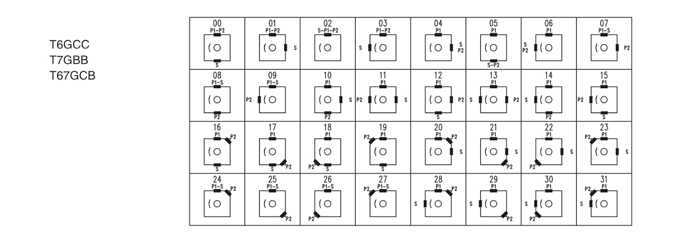
Port positions(Views from shaft end of pump)
Installation Dimensions

| Oil port | Flange | Installation Dimensions (mm) | ||||||
| A1 | B1 | C1 | D1 | Thread | ||||
| T6GCC T67GCB T7GBB |
P1 | 1″ | F08 | 26.2 | 52.4 | 25.4 | 76.2 | 3/8″-16UNCx19.0 |
| P2 | 01&11:3/4″ | F06 | 22.2 | 47.6 | 19 | 76.2 | 3/8″-16UNC×19.0 | |
| 00&10:1″ | F08 | 26.2 | 52.4 | 25.4 | 74.7 | |||
| S | 10&11:2-1/2″ | F20 | 50.8 | 88.9 | 63.5 | 84.1 | 1/2″-13UNC×23.9 | |
| 00801:3″ | F24 | 61.9 | 106.4 | 76.2 | 84.1 | 5/8″-11UNC×28.4 | ||
Write your message here and send it to us

